Unified Modelling Language (UML) Types
Unified Modelling Language (UML) is a standardized visual modelling language used in software engineering to describe, specify, visualise, and document the structure and behaviour of a system. UML provides a variety of diagram types to represent different aspects of a system. Here are some commonly used UML diagram types:
1. Class Diagram
Represents the static structure of a system by showing classes, attributes, operations, relationships, and their associations.
VISUAL PARADIGM, 2019. UML Class Diagram Tutorial Available from: https://www.visual-paradigm.com/guide/uml-unified-modeling-language/uml-class-diagram-tutorial/

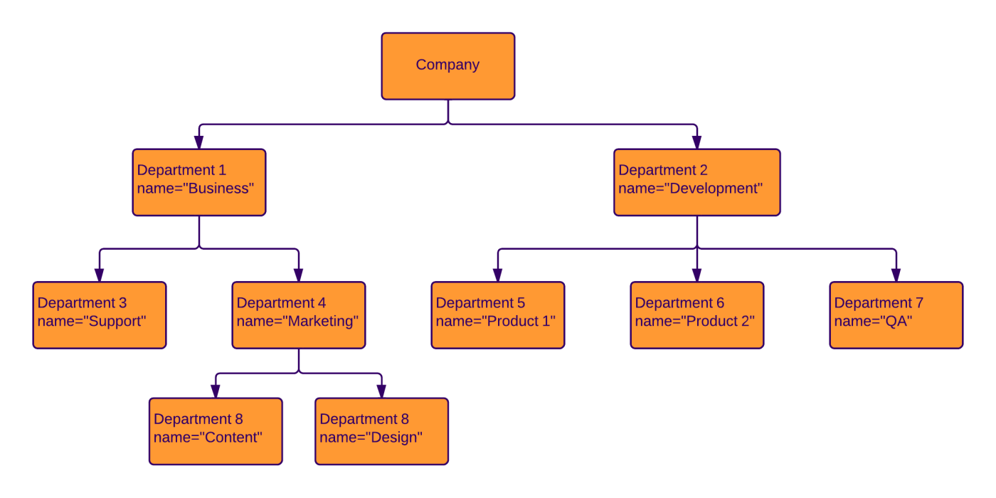
2. Object Diagram:
Depicts instances of classes and their relationships at a specific point in time. It shows the objects and their attributes and associations.
LUCIDCHART, 2023. Object Diagram Tutorial [viewed 30 May 2023]. Available from: https://www.lucidchart.com/pages/uml-object-diagram
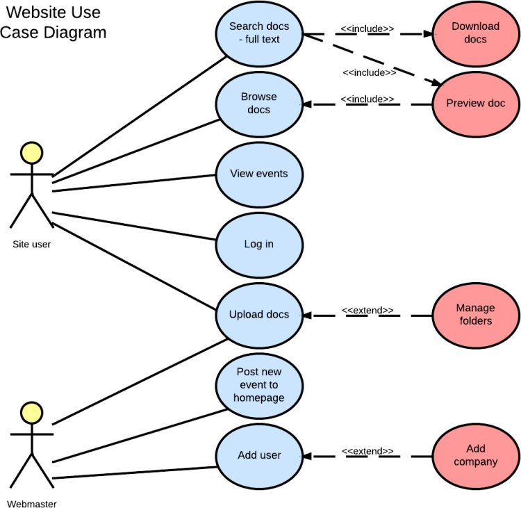
3. Use Case Diagram
Illustrates the functional requirements of a system by showing actors, use cases, and their relationships. It represents the interactions between the system and external entities.
| LUCIDCHART, 2019. UML Use Case Diagram Tutorial | Lucidchart [viewed 30 May 2023]. Available from: https://www.lucidchart.com/pages/uml-use-case-diagram |
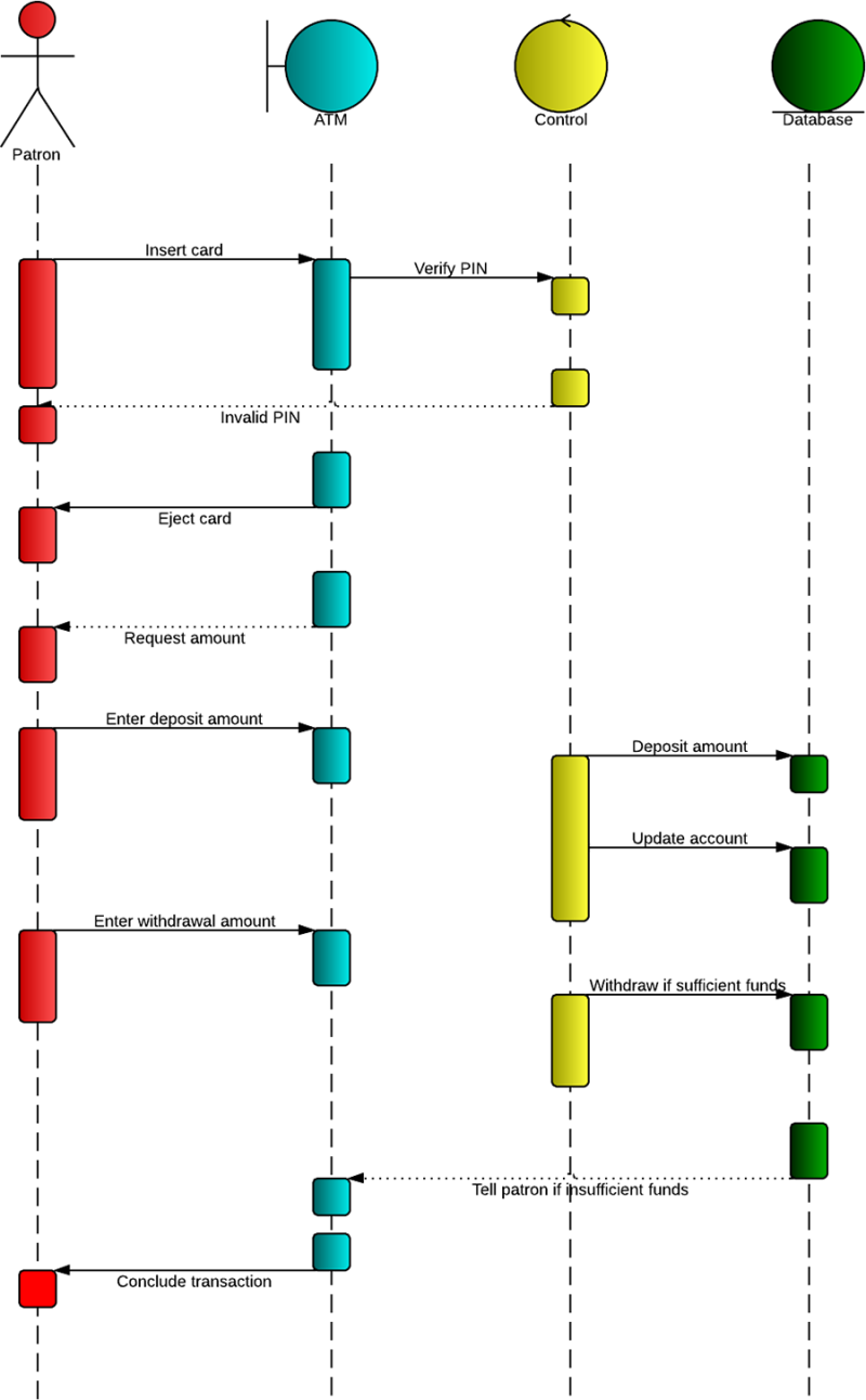
4. Sequence Diagram
Shows the interactions between objects in a sequential manner over time. It emphasizes the time ordering of messages exchanged between objects.
LUCIDCHART, 2019b. UML Sequence Diagram Tutorial [viewed 30 May 2023]. Available from: https://www.lucidchart.com/pages/uml-sequence-diagram
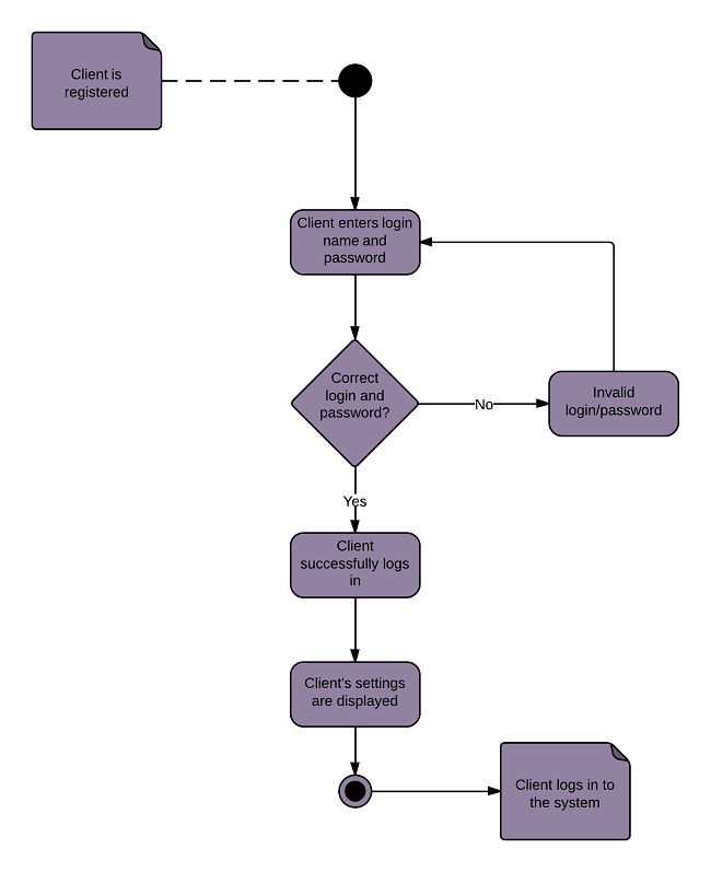
5. Activity Diagram
Represents the workflow or flow of activities in a system. It describes the dynamic behaviour of a system by showing the control flow, decisions, concurrency, and loops.
LUCIDCHART, 2023b. UML Activity Diagram Tutorial [viewed 30 May 2023]. Available from: https://www.lucidchart.com/pages/uml-activity-diagram
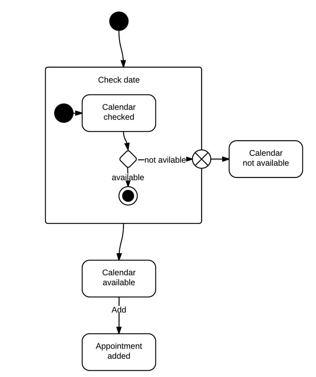
5. State Machine Diagram
Models the behaviour of an object or a system by representing the states, events, and transitions between states. It describes the possible sequences of states and their responses to events.
LUCIDCHART, 2023c. State Machine Diagram Tutorial [viewed 30 May 2023]. Available from: https://www.lucidchart.com/pages/uml-state-machine-diagram
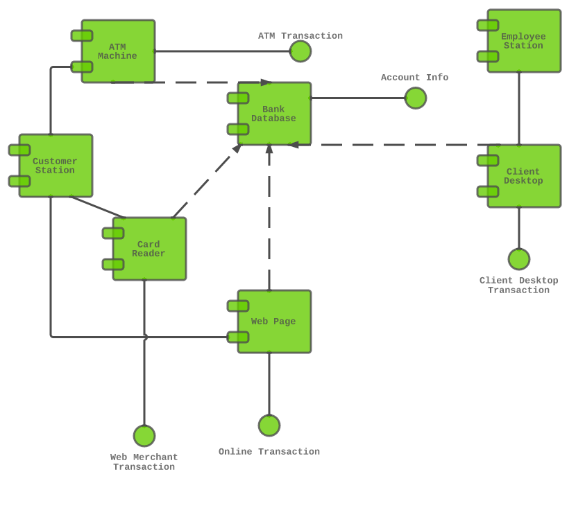
5. Component Diagram
Depicts the organization and dependencies of software components in a system. It shows the high-level structure of a system and the interfaces between components.
LUCIDCHART, 2019c. Component Diagram Tutorial [viewed 30 May 2023]. Available from: https://www.lucidchart.com/pages/uml-component-diagram
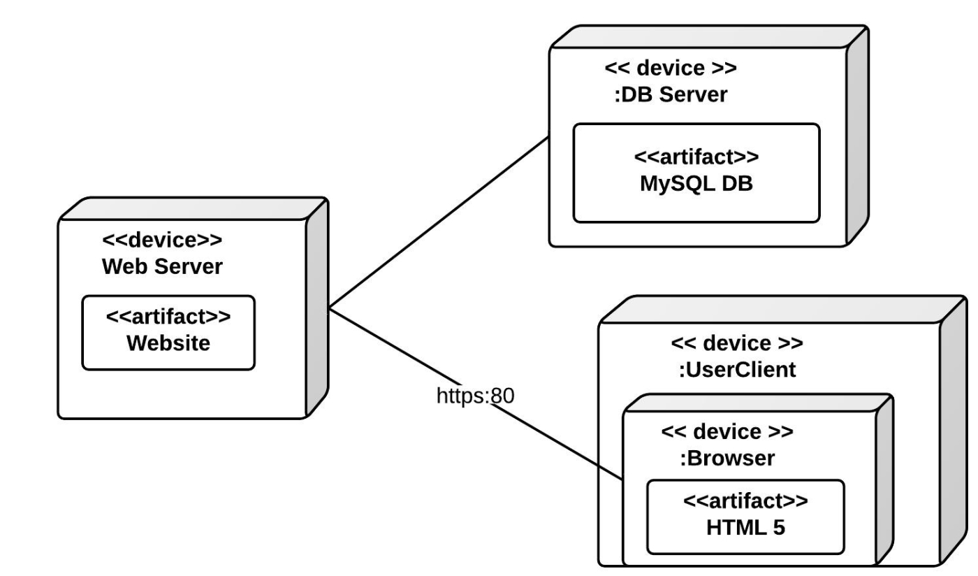
6. Deployment Diagram
Represents the physical deployment of software components on hardware nodes. It illustrates the hardware infrastructure and the distribution of components across nodes.
LUCIDCHART, 2023d. Deployment Diagram Tutorial [viewed 30 May 2023]. Available from: https://www.lucidchart.com/pages/uml-deployment-diagram
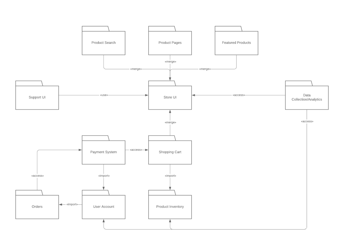
7. Package Diagram
Shows the organization and dependencies of packages or namespaces in a system. It provides a high-level view of the modular structure of a system.
LUCIDCHART, 2023e. Package Diagram Tutorial [viewed 30 May 2023]. Available from: https://www.lucidchart.com/pages/uml-package-diagram
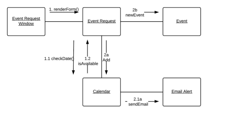
8. Communication Diagram
Like a sequence diagram, it focuses on the interactions between objects but emphasizes the relationships between objects rather than the time ordering of messages.
LUCIDCHART, 2023f. Communication Diagram Tutorial [viewed 30 May 2023]. Available from: https://www.lucidchart.com/pages/uml-communication-diagram
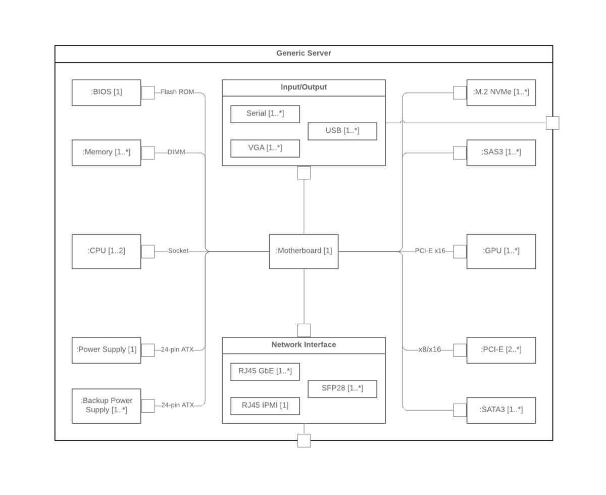
9. Composite Structure Diagram
Describes the internal structure and collaborations of a class or component. It shows the structure and relationships between parts, ports, connectors, and other internal elements.
LUCIDCHART, 2023g. Composite Structure Diagram Tutorial [viewed 30 May 2023]. Available from: https://www.lucidchart.com/pages/uml-composite-structure-diagram
T